The Processor
The Processor
What do we mean by a computer
? There are a bunch of parts that we know are there, but need some explanation.
What is in there, and why is it the way it is?
The Processor
At the lowest level, a computer is just a bunch of electronics. There are wires, and electric currents in the wires.
Somehow, computer engineers make those currents do useful things, and we get a computer. What's really going on in a computer? That's their problem.
The Processor
But it's our problem too. *
There are a lot of layers of abstraction between your C code and the circuit, but all abstractions are leaky and sometimes we need to know what's going on in there, at least a little.
Digital Circuits
My goal for the rest of this slide deck is not to teach you how to build digital circuits. If you want to learn that, I'm not the instructor you need.
My goal is: convince you it's possible to build a computer with circuitry. This will guide us toward some of the reasons computers are the way they are.
It's also a way to show what some terms really mean and why we use them.
Digital Circuits
Also: if you're looking for accurate information about digital circuits, look elsewhere. Everything here is simplified the maximium amount possible, and then a little more.
i.e. this slide deck contains useful oversimplifications.
Digital Circuits
First leaky abstraction: physics is cruel. We can design a circuit to send five volts down a wire, but it won't really be exactly 5.000000 V. It might be 4.9 V one moment and 5.1 V the next.
So if we try to imagine some circuit where we represent numbers 0–50 as voltages 0.0 V, 0.1 V, 0.2 V, …, 5.0 V, we're very quickly start having errors because the voltages aren't as precise as we'd like.
Digital Circuits
The thing that's actually practical to build is a binary circuit where low/high voltages represent 0/1.

Digital Circuits
So because physics and engineering are what they are, we're going to have circuits that manipulate only two distinct values that we'll call 0 and 1.
Each is a bit. 0 is a bit. 1 is a bit. 0110 is four bits.
Digital Circuits
A single bit is so small it's hard to talk about: usually we'll use groups of many bits. First step: a collection of eight bits is a byte. 01101100 is a byte.
Usually bit
is abbreviated b
and byte
is abbreviated B
, so 1 B = 8 b. (Not everybody does this consistently, but I will.)
Digital Circuits
Transistors are where digital circuits start: a circuit that essentially switches a current on/off.

The idea: if there's a (small) current on B, connect C to E. Otherwise, C and E aren't connected. [That's a bipolar junction transistor
: there are others.]
Digital Circuits
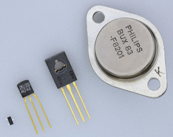
They can be big or small. Four transistors:
Digital Circuits
Or extremely small. 1.4 billion transistors:
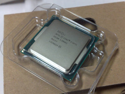
A modern processor: maybe 50–150 billion transistors.
Digital Circuits
Once we have transistors, it's possible to combine them to build useful components like an AND gate, represented like this (inputs A and B, output C):

The AND gate's job: output a 1 only when both inputs are 1.
Digital Circuits
An AND gate is built with transistors like this:

Digital Circuits
We can give a complete description of the AND gate's behaviour:
| A | B | C |
|---|---|---|
| 0 | 0 | 0 |
| 0 | 1 | 0 |
| 1 | 0 | 0 |
| 1 | 1 | 1 |
Digital Circuits
The OR gate outputs 1 when at least one of the inputs is 1:

| A | B | C |
|---|---|---|
| 0 | 0 | 0 |
| 0 | 1 | 1 |
| 1 | 0 | 1 |
| 1 | 1 | 1 |
Digital Circuits
The XOR gate (exclusive-or) outputs 1 when exactly one of the inputs is 1:

| A | B | C |
|---|---|---|
| 0 | 0 | 0 |
| 0 | 1 | 1 |
| 1 | 0 | 1 |
| 1 | 1 | 0 |
Digital Circuits
The NOT gate flips its input:

| A | B |
|---|---|
| 0 | 1 |
| 1 | 0 |
Digital Circuits
Combinatorial logic: a logic function where the output depends only on the current inputs. i.e. there is no state or memory
, just inputs being mapped to outputs.
Useful fact: using these gates (AND, OR, XOR, NOT), it's possible to build a circuit to implement any combinatorial logic.
The Processor
It's possible to connect these simple logic gates to do useful stuff. We will come back some things that would be useful
later, but mostly that's another course.
But I want to skim through an example to prove that it's possible: the Simple CPU project.
The Processor
The first sections on that page describe how to build…
- a
multiplexer
which can select between multiple inputs: if select==0 output A; if select==1 output B. - multiplexers with \(n\) selector signals that can switch up to \(2^n\) inputs.
- a
ripple adder
that can add integers (assuming we have some way to represent integers with bits, which we haven't talked about yet).
These are both combinatorial logic problems, so they're definitely possible to construct.
The Processor
Then it uses those to build a circuit that gets two 8-bit inputs A and B and calculates all of A+B, A-B, A&B (bitwise AND), and several others. i.e. some circuit that does this (the \8
indicates 8 wires carrying 8 bits):

The Processor
Hook a multiplexer up to the output of that: the (five-selector input) multiplexer selects which calculation is the actual output
of the circuit. That's our ALU, arithmetic logic unit, usually drawn like this:

The Processor
The the circuitry described on that page, if we set the S (select) bits to 00000, the ALU outputs A+B.
If the S bits are 10100, it outputs A+1.
If the S bits are 01000, it outputs A-B-1.
The Processor
It starts to look processor-like, but I still wouldn't call it a processor
. Where is our data coming from? Where is it going to?
The Processor
If we're going to store bits, we need a flip-flop: a circuit that can store a single bit.

The idea: we can set the output (Q) to the input (D) but only at the moment the clock signal (the triangle) changes from 1 to 0 (the falling edge).
The Processor
| clock | D | Q | Q |
|---|---|---|---|
| falling | 0 | 0 | 1 |
| falling | 1 | 1 | 0 |
| (anything else) | no change | ||
The Processor
Wait… clock?
Physics interrupts us again: these circuits are physical things and it takes time for electrons to bounce through them. Our circuits need time from when the inputs are applied until the outputs are ready.
The Processor
A clock provides a regular pulse (alternating 0, 1, 0, 1, 0, 1, …) that is used to synchronize the circuit. A clock cycle needs to be long enough for the circuit to finish
whatever it's doing and have correct outputs.
The clock signal can be used to make sure we store the correct results in our flip-flops.
Implication: the circuit needs to be fairly simple, so it completes its calculation quickly, and we can have a short clock cycle.
The Processor
We could combine several flip flops to store several bits and call it a register. Let's have 8-bit registers to match the ALU inputs.
And we could connect the output of our ALU to the input of a register, and store the result of a calculation.

The Processor
The idea: get values we want into the A and B registers and set S to select the operation we want (e.g. addition). Get the next
value for B on its input. Wait until the falling clock: then A get the result of the computation and B get its new value. Change S to something else to do the next calculation. Repeat.
The Processor
We don't want to overwrite the register in every clock cycle: only when there's a result we need to store.
We need to figure out the rest of the inputs. But then maybe we could think of this as a processor.
The Processor
There was a choice of the number of bits in each register (and corresponding size of ALU inputs/outputs). That choice determines the amount of data you most easily work with in the CPU. This is the word size.
The Processor
The x84-64 architecture (everything after ∼2003: Athlon 64 and Pentium 4) has a 64-bit word size. So do most other modern CPUs (modern ARM, RISC-V).
Its predecessor, IA-32 (∼1985: i386), had 32-bit words. The earliest x86 CPUs (1978: 8086) had 16-bit words.
This simple CPU
example and earlier CPUs had 8-bit words.
The Processor
Generally, modern processors can do calculations on values smaller than their word size: smaller values take less memory (and the operations may be faster).
add %rcx, %rax  # 64-bit add
add %ecx, %eax  # 32-bit add
add %cx, %ax    # 16-bit add
add %cl, %al    # 8-bit add
And you can do calculations on larger values by writing multiple instructions that do it.
Instructions
We need to figure out the S inputs to the ALU: the ones that decide which calculation it's going to do.
There will also be other control inputs on other circuits. They will also need to be set correctly to do whatever operation the programmer wants.
Instructions
Each operation the processor is going to do is called an instruction. That's what the programmer (or compiler) will create.
But how does the programmer's instruction (I want to add X and Y
) make the processor actually do stuff?
Instructions
First we need to get the instruction into the processor. It will be stored in another register: the instruction register or IR. In the example simple CPU, instructions are 16 bits, so the IR is a 16 bit register.
Instructions
Another circuit will take the instruction and turn it into control signals that can make the rest of the circuit do what we want.

e.g. five of those control signals will connect to the ALU's S input. If the instruction indicates calculate A+1
, the ALU's S input needs to be 10100, so the decode logic needs to produce those values.
Memory
The instructions that are destined for the IR have to come from somewhere. So does the data we put in the A and B registers. Also we need to store more data than the registers can hold.
Memory
The computer's memory will be kind of like registers: some kind of circuit that can store bits until we need them.
But registers are too expensive to have too many of them. We want lots of memory (relative to the number of registers).
Memory
The memory in modern computers is DRAM. The details are the engineers' problem, but each bit is stored in a capacitor.
Capacitor: think of a tiny rechargable battery. Discharged = 0, charged = 1.
Like a rechargable battery, a capacitor will discharge over time (in ≈64 ms for common DDR SDRAM). They must be periodically refreshed
or they will lose their data. The circuit takes care of that.
Memory
The memory will be arranged so we see it as a collection of bytes: it will be read/written at least 8 bits at a time. In this example system, we always read/write two adjacent bytes (16 bits) in each memory operation.
Each byte in memory will have an address: an integer that indicates which byte in memory we're talking about.
In other words, memory looks like an array of bytes and the address is an index into that array.
Memory
Memory
Our memory circuit will be something like this:

The ADDRESS input will be thought of as an integer: which memory address do we want to read/write?
DATA_OUT and DATA_IN will be used to carry the data we're reading/writing.
Memory
To write, set WE (write-enable) to 1 and the data at location ADDRESS will be changed to the bits from DATA_IN.
To read, set WE to 0 and the ADDRESS input to which location from memory you want. The memory contents will be on DATA_OUT.
Memory
We had the choice of how many bits are in the address: 8 will limit us to \(2^8 = 256\) memory locations.
We can also choose the number of bits in the data in/out connections. This example chose 16, so a whole instruction can be read at once.
Memory
Note that the data connections are 16 bits. Every memory read/write in this architecture will be for the byte at memory location ADDRESS and also ADDRESS+1.
That's probably not what you want in a real
computer.
Memory
Or something like:
wait_for_clock_falling_edge()
if WE == 0:
    DATA_OUT = MEMORY[ADDRESS] : MEMORY[ADDRESS+1]
else:
    MEMORY[ADDRESS] : MEMORY[ADDRESS+1] = DATA_IN
(With
meaning :those bits concatenated and thought of as a single wider value
.)
Memory
Along with the data we're working with, the program we're running will also be stored in memory: a Von Neumann architecture.
[Historically, it wasn't obvious that this was the way to store programs. We could have programed computers by connecting wires, or punch cards, or with totally separate instruction memory.]
Memory
Our memory is doing a lot: storing both instructions and data. We at least need to read an instruction before executing it, and executing it might involve reading/writing data too.
It sounds like reading/writing memory might be what limits performance. This is the von Neumann bottleneck. It's even worse than it sounds: modern memory is many times slower than the processor clock cycle. More later [later topic: “memory hierarchy”].
Memory
We will need circuitry that can decide what to do with the memory address that's being read: it might be destined for the IR or A or B register: some kind of big multiplexer with appropriate control inputs?
The memory's DATA_OUT will have to connect to those (perhaps multiplexed with other input values), and each be triggered to store the value when appropriate.
Memory
Similarly, we might be writing the result of a calculation back to memory: then something needs to trigger the memory WE (write enable) signal, get the data to DATA_IN and memory location to ADDRESS.
For our purposes, we'll simply say those can be built, and the control signals coming from the decoder will take care of triggering all the right behaviour.
Instruction Cycle
Let's talk more about what has to happen to get an instruction running (in our simple CPU
example or any other processor).
To get an instruction into the instruction register, it must be read from memory. But which memory location?
Instruction Cycle
We need another register for that: the instruction pointer or IP (or program counter, PC) will hold the memory address of the next instruction we want to execute (i.e. a pointer to the next instruction).
Every time the processor starts an instruction, the IP will be incremented so it points at the next instruction. (In this example, IP+=2 because every instruction is two bytes.)
Instruction Cycle
So, to complete an instruction, the processor must:
- Fetch the instruction from memory location IP into the IR. Increment the IP.
- Decode the instruction.
- Execute the instruction: do the calculation, or write to memory, or whatever.
We will also need some circuitry to manage this process (and others in the processor): the control logic.
Instruction Cycle
This fetch-decode-execute process is called the instruction cycle.
As with everything else, modern processors make this much more complex, but the general idea is still in there.
Instruction Cycle
The example simple CPU does each of these steps in a separate cycle, plus another to increment the IP. So, every instruction takes four cycles: fetch, decode, execute, increment.
This is also much more complex in a real CPU.
Instruction Cycle
Our final but incomplete sketch of a processor:

Reality
The Simple CPU project that I have been describing is an extremely simple processor design, and I left out a lot of details.
I hope you're convinced it could be built. If we spent a few more lectures dealing with the details, I'm confident you could understand all of them, but it's not necessary for this course.
Reality
If we spent a bunch more time adding detail, we could perhaps see something like a MOS 6502 that was in the Apple II, Atari 5200, Commodore 64, NES, and many other early-1980s computers.
- 8-bit words
- 1 MHz clock (i.e. 1,000,000 clock cycles per second)
- ∼3500 transistors
The block diagram of the 6502 isn't so different than what was described in this lecture.
Reality
The 6502 has ∼60 instructions the programmer (or compiler) can use.
Each one takes a fixed number of clock cycles ≥2 (roughly, 2 cycles + time needed to get the operands if they're in memory).
Reality
Then we'd be right up to date, as of the late 1970s.
Now imagine 40 or 50 years of complexity piled on top of those ideas. That's what's in your computer.
We'll talk about more of the things added in modern processors as the course goes on.
Reality
For a modern
processor, I'm going to generally think of something like a Haswell CPU (∼2013, Intel Core 4xxx). It has all of the functionality we need for this course (as does any successor or AMD Ryzen series).
- 64-bit words
- ∼3 GHz clock (i.e. 3,000,000,000 clock cycles per second)
- ∼1.4 billion transistors
Reality
Compare the block diagram
of a Haswell processor. It's a lot more complex, but very roughly speaking,
- front end ≈ control+decode,
- execution engine ≈ some more control+decode and the ALU,
- memory subsystem ≈ the circuitry that talks to memory (not the memory itself).
This describes a single core. A four core CPU
has four of these.
Reality
A Haswell processor has many hundreds of instructions, depending how you count.
The number of cycles each one takes is much more complicated and can depend on many factors (some of which we'll discuss later).
Reality
A more modern x86-64 or Apple M-series CPU has
The Point
Hopefully you have a better idea what's going on in a computer:
- why computers use binary
- registers: flip-flops that store bits (in the processor)
- word size, or what a
64-bit processor
is - instruction pointer: where the next instruction lives
- clock speed: determined by how long the circuits take to
finish
- memory: capacitors that store bits
- von Neumann bottleneck: memory is busy